X-Ray Data Booklet
Section 4.1 MULTILAYERS AND CRYSTALS
A. MULTILAYERS
By means of modern vacuum deposition technology, structures consisting of alternating layers of high- and low-Z materials, with individual layers having thicknesses of the order of nanometers, can be fabricated on suitable substrates. These structures act as multilayer interference reflectors for x-rays, soft x-rays, and extreme ultraviolet (EUV) light. Their high reflectivity and moderate energy bandwidth (10 < E/DE < 100) make them a valuable addition to the range of optical components useful in instrumentation for EUV radiation and x-rays with photon energies from a few hundred eV to tens of keV. These multilayers are particularly useful as mirrors and dispersive elements on synchrotron radiation beamlines. They may be used to produce focal spots with micrometer-scale sizes and for applications such as fluorescent microprobing, microdiffraction, and microcrystallography. Multilayer reflectors also have a wide range of applications in the EUV region, where normal-incidence multilayer reflectors allow the construction of space telescopes and of optics for EUV lithography.
Ordinary mirrors, operating at normal or near-normal angles of incidence, do not work throughout the EUV and x-ray regions. The reason is the value of the complex refractive index, n = 1 – d – ib, which can be close to unity for all materials in this region; d may vary between 10–3 in the EUV region to 10–6 in the x-ray region. The Fresnel equations at normal incidence show that the reflectivity R2 = |(n– 1)/(n + 1)|2 is very small. However, the more general Fresnel equations show that x-rays and EUV radiation can be reflected by mirrors at large angles of incidence. Glancing (or grazing) incidence is the term used when the rays make a small angle (a few degrees or less) with the mirror surface; the complement (90° – i) of the optical angle of incidence i is called the glancing (or grazing) angle of incidence. Glancing-incidence mirrors are discussed in Section 4.2.
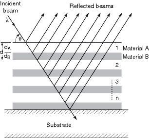
Although the normal-incidence intensity reflectivity R2 of a surface might be 10–3 or 10–4, the corresponding amplitude reflectivity R = (n – 1)/(n + 1), the square root of the intensity reflectivity, will be 1/30 to 1/100. This implies that, if the reflections from 30–100 surfaces could be made to add in phase, a total reflectivity approaching unity could be obtained. This is the multilayer principle. As shown in Fig. 4-1, a multilayer reflector comprises a stack of materials having alternately high and low refractive indices. The thicknesses are adjusted so that the path length difference between reflections from successive layer pairs is equal to one wavelength. Hence, x-ray/EUV multilayers are approximately equivalent to the familiar “quarter-wave stacks” of visible-light coating technology. The equivalence is not exact, however, because of the absorption term b, which is usually negligible for visible-light multilayers. This absorption reduces the multilayer reflectivity below unity and requires the design to be optimized for highest reflectivity. Particularly critical is the value of G, which is the ratio of the thickness of the high-Z (high electron density, high |n|) layer to the total thickness of each layer pair. This optimization normally requires modeling or simulation of the multilayer. Most thin-film calculation programs, even if designed for the visible region, will perform these calculations if given the right complex values of the refractive index. Alternatively, there are a number of on-line calculation programs available; links can be found at http://www-cxro.lbl.gov/.
Either elemental materials or compounds can be used to fabricate multilayer reflectors. The performance obtained from a multilayer depends largely on whether there exists a fortuituous combination of materials having the right refractive indices (good contrast, low absorption), whether these materials can be deposited in smooth thin layers, and whether they remain stable (low reactivity, low diffusion) in the deposited state. The roughness of the underlying substrate is also of prime importance; an rms roughness of the same order of magnitude as the layer

Fig. 4-1. Schematic of a multilayer reflector of n bilayer pairs. The parameters l, q, and d are chosen to satisfy the familiar Bragg equation, but the relative thicknesses of the high- and low-Z materials are also critical in optimizing reflectivity. The total reflectivity is the vector sum of the complex reflection coefficients at each interface, with the different path lengths taken into account.
thicknesses will spoil the performance of most coatings. “Superpolished” substrates, with roughness s ≈ 0.1 nm are preferred. On such substrates, the peak reflectivity of the coatings can approach 80% to 90% of theoretical predictions.
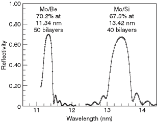
A large variety of multilayers have been made and their reflectivities measured over the years. A database of reported reflectivities has been assembled from surveys taken at the biennial Physics of X-ray Multilayer Structures conferences and can be found at the website listed above. For the EUV region around 100 eV, two remarkably successful combinations are molybdenum-silicon and molybdenum-beryllium. With Mo-Si, a normal-incidence reflectivity of 68% has been achieved at a wavelength of 13.4 nm; Mo-Be multilayers have achieved a reflectivity close to 70% at 11.4 nm (see Fig. 4-2). These relatively high reflectivities are the basis for current efforts in the field of EUV lithography.

Fig. 4-2. The reflectivity of two multilayer reflectors at extreme ultraviolet wavelengths.

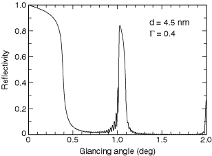
Fig. 4-3. The reflectivity of a tungsten–boron carbide multilayer at 8048 eV. The parameters d and G are discussed in the text.
At hard x-ray wavelengths near 10 keV, a commonly used multilayer is made with tungsten as the high-Z material and boron carbide (B4C) as the low-Z material. A reflectivity of 84% has been achieved with this combination at 8048 eV, the energy of the Cu Ka line (see Fig. 4-3).
B. CRYSTALS
Multilayers are examples of a periodic structure that can be used to analyze short-wavelength electromagnetic radiation. Such structures split the incident beam into a large number N of separate beams; between any beam i and the beam i + 1, the optical path difference is constant. After leaving the periodic structure, the beams are recombined and caused to interfere, whereupon the spectrum of the incident radiation is produced.
Dispersion of radiation by a periodic structure is thus formally equivalent to multiple-beam interferometry. Structures that are periodic across their surface and that produce the N interfering beams by division of the incident wave front are called gratings and are treated in Section 4.3. Crystals and multilayer structures produce the N interfering beams by division of the incident amplitude. The spectrum of the incident radiation is dispersed in angle according to the Bragg equation nl = 2d sin q, where n is an integer representing the order of the reflection,l is the wavelength of the incident radiation, d is the period of the multilayer or crystal structure, and q is the angle of glancing incidence. For a crystal, d is the lattice spacing, the perpendicular distance between the successive planes of atoms contributing to the reflection. These planes are designated by their Miller indices [(hkl) or, in the case of crystals belonging to the hexagonal group, (hkil)]. (The value of 2d also represents the longest wavelength that the structure can diffract.)
For 2d values greater than about 25 Å, the choice of natural crystals is very limited, and those available (such as prochlorite) are likely to be small and of poor quality. Sputtered or evaporated multilayers can be used as dispersing elements at longer wavelengths. (Langmuir-Blodgett films have fallen into disfavor since the development of vacuum-deposited multilayers.)
Table 4-1 is a revision of one compiled by E. P. Bertin [1]. The crystals are arranged in order of increasing 2d spacing.
REFERENCE
1. E. P. Bertin, “Crystals and Multilayer Langmuir-Blodgett Films Used as Analyzers in Wavelength-Dispersive X-Ray Spectrometers,” in J. W. Robinson, Ed., Handbook of Spectroscopy (CRC Press, Cleveland, 1974), vol. 1, p. 238.

