X-Ray Data Booklet
Section 4.4 ZONE PLATES
A zone plate is a circular diffraction grating. In its simplest form, a transmission Fresnel zone plate lens consists of alternate transparent and opaque rings. The radii of the zone plate edges are given by
![]() (1)
(1)
where n is the zone number (opaque and transparent zones count separately), l is the wavelength, and f is the first-order focal length. The zone plate lens can be used to focus monochromatic, uniform plane wave (or spherical wave) radiation to a small spot, as illustrated in Fig. 4.8, or can be used for near-axis point-by-point construction of a full-field image, as illustrated in Fig. 4.9. When used in imaging applications, it obeys the thin-lens formula
![]() (2)
(2)
where p and q are the object and image distances, respectively. Note that the second term on the right-hand side of Eq. (1) is correct only for p << q or p >> q, which are the common cases in zone plate applications. Descriptions of the diffractive properties of zone plate lenses, their use in x-ray microscopes, and extensive references to the literature are given elsewhere [1–3].
A zone plate lens is fully specified by three parameters. Most applications are dominated by the choice of photon energy Ów, and thus by l. Resolution is set in large part by l and the outer zone width, Dr º rN – rN–1. To avoid chromatic blurring, the number of zones, N, must be less than the inverse relative spectral bandwidth, l/Dl. Thus, for many applications, l, Dr, and N constitute a natural set of zone plate–defining parameters. In terms of these three basic parameters, other zone plate parameters are given by [3]
![]() (3)
(3)
![]() (4)
(4)
![]() (5)
(5)
![]() (6)
(6)
To avoid chromatic blurring requires that
N < l/Dl , (7)
where Dl is the spectral width of the illuminating radiation. For uniform plane-wave illumination, as in Fig. 4-8, the Rayleigh criterion sets the diffraction-limited (l, NA) spatial resolution of a perfect lens as
![]() ,
(8)
,
(8)
where NA = sinq is the numerical aperture of the lens in vacuum and q is the half-angle of the focused radiation. This resolution is obtained over an axial depth of focus given by
![]() (9)
(9)
Spatial resolution in the full-field case can be improved somewhat from that given in Eq. (8), depending on both the object itself and the partial coherence of the illumination [4], as set by the parameter
![]() (10)
(10)
where (NA)c refers to the illumination numerical aperture of the condenser, and (NA)o is that of the zone plate objective lens, as given in Eq. (6).
The efficiency of the simple zone plate in the first order is ideally p–2, or about 10%. The remainder of the radiation is absorbed (50%) or diffracted in other orders—zero order (25%), negative orders (12.5%), and higher positive orders (2.5%). If opaque zones are replaced by transparent but phase-shifting zones, efficiencies can be substantially improved [5]. To isolate the first order from unwanted orders, zone plate lenses are often made with a central stop, used in conjunction with a somewhat smaller collimating aperture near the focal region. This is particularly effective in scanning x-ray microscopes [6,7], where the zone plate is used to focus the radiation to a small spot, as in Fig. 4-8. For full-field x-ray microscopes, as suggested by Fig. 4-9, first-order imaging is assisted in a similar manner by stopping the central portion of the illuminating radiation [8].
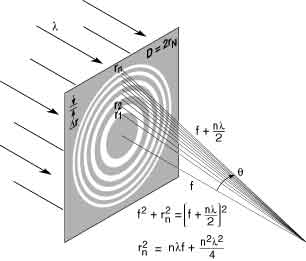
Fig. 4-8. A Fresnel zone plate lens with plane wave illumination, showing only the convergent (+1st) order of diffraction. Sequential zones of radius rn are specified such that the incremental path length to the focal point is nl/2. Alternate zones are opaque in the simple transmission zone plate. With a total number of zones, N, the zone plate lens is fully specified. Lens characteristics such as the focal length f, diameter D, and numerical aperture NA are described in terms of l, N, and Dr, the outer zone width. [Courtesy of Cambridge University Press, Ref. 3.]
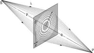
Fig. 4-9. A Fresnel zone plate used as a diffractive lens to form an x-ray image of a sourse point S in the image plane at P. The lens is shown as having a diameter D and outer zone width Dr. The object and image distances are p and q, respectively. A full-field image is formed concurrently in this manner. [Courtesy of Cambridge University Press, Ref. 3.]
REFERENCES
1. A. G. Michette, Optical Systems for Soft X-Rays (Plenum, London, 1986).
2. G. R. Morrison, “Diffractive X-Ray Optics,” Chapter 8 in A. G. Michette and C. J. Buckley, Eds., X-Ray Science and Technology (Inst. Phys., London, 1993).
3. D. T. Attwood, Soft X-Rays and Extreme Ultraviolet Radiation: Principles and Applications (Cambridge Univ. Press, Cambridge, 1999).
4. L. Jochum and W. Meyer-Ilse, “Partially Coherent Image Formation with X-Ray Microscopes,” Appl. Opt. 34, 4944 (1995).
5. J. Kirz, “Phase Zone Plates for X-Rays and the Extreme UV,” J. Opt. Soc. Amer. 64, 301 (1974).
6. H. Rarback, D. Shu, S. C. Feng, H. Ade, J. Kirz, I. McNulty, D. P. Kern, T. H. P. Chang, Y. Vladimirsky, N. Iskander, D. Attwood, K. McQuaid, and S. Rothman, “Scanning X-Ray Microscopy with 75-nm Resolution,” Rev. Sci. Instrum. 59, 52 (1988).
7. C. Jacobsen,
S. Williams, E. Anderson, M. Browne, C. J. Buckley, D. Kern, J. Kirz, M. Rivers,
and X. Zhang, “Diffraction-limited Imaging in a Scanning Transmission X-Ray
Microscope,” Opt. Commun. 86, 351 (1991); http://xray1.physics.sunysb.edu/downloads/
stxm_optcom91.pdf.
8. B. Niemann, D. Rudolph, and G. Schmahl, “X-Ray Microscopy with Synchrotron Radiation,” Appl. Opt. 15, 1883 (1976).