Synchrotron radiation occurs when a charge moving at relativistic speeds follows a curved trajectory. In this section, formulas and supporting graphs are used to quantitatively describe characteristics of this radiation for the cases of circular motion (bending magnets) and sinusoidal motion (periodic magnetic structures).
We will first discuss the ideal case, where the effects due to the angular divergence and the finite size of the electron beam—the emittance effects—can be neglected.
A. BENDING MAGNETS
The angular distribution of radiation emitted by electrons moving through a bending magnet with a circular trajectory in the horizontal plane is given by
 (1)
(1)
where
ŠB = photon flux (number of photons per second)
q = observation angle in the horizontal plane
y = observation angle in the vertical plane
a = fine-structure constant
g = electron energy/mec2 (me = electron mass, c = velocity of light)
w = angular frequency of photon (e = Ów = energy of photon)
I = beam current
e = electron charge = 1.602 ´ 10–19 coulomb
y = w/wc = e/ec
wc = critical
frequency, defined as the frequency that divides the emitted power into equal
halves,
= 3g3c/2r
r = radius of instantaneous curvature of the electron
trajectory (in practical units,
r[m]
= 3.3 E[GeV]/B[T])
E = electron beam energy
B = magnetic field strength
ec = Ówc (in practical units,
ec [keV] = 0.665 E2 [GeV] B[T])
X = gy
x = y(1 + X2)3/2/2
The subscripted K’s are modified Bessel functions of the second kind. In the horizontal direction (y = 0), Eq. (1) becomes
 (2)
(2)
where
![]() (3)
(3)
In practical units [photons·s–1·mr–2·(0.1% bandwidth)–1],
The function H2(y) is shown in Fig. 2-1.
Fig. 2-1. The functions G1(y) and H2(y), where y is the ratio of photon energy to critical photon energy.
The distribution integrated over y is given by
![]() (4)
(4)
where
![]()
(5)
In practical units [photons·s–1·mr–1·(0.1% bandwidth)–1],
![]()
The function G1(y) is also plotted in Fig. 2-1.
Radiation from a bending magnet is linearly polarized when observed in the bending plane. Out of this plane, the polarization is elliptical and can be decomposed into its horizontal and vertical components. The first and second terms in the last bracket of Eq. (1) correspond, respectively, to the intensity of the horizontally and vertically polarized radiation. Figure 2-2 gives the normalized intensities of these two components, as functions of emission angle, for different energies. The square root of the ratio of these intensities is the ratio of the major and minor axes of the polarization ellipse. The sense of the electric field rotation reverses as the vertical observation angle changes from positive to negative.
Synchrotron radiation occurs in a narrow cone of nominal angular width ~1/g. To provide a more specific measure of this angular width, in terms of electron and photon energies, it is convenient to introduce the effective rms half-angle sy as follows:
 (6)
(6)
Fig. 2-2. Normalized intensities of horizontal and vertical polarization components, as functions of the vertical observation angle y, for different photon energies. (Adapted from Ref. 1.)
Fig. 2-3. The function C(y). The limiting slopes, for e/ec << 1 and e/ec >> 1, are indicated.
where sy is given by
![]() (7)
(7)
The function C(y) is plotted in Fig. 2-3. In terms of sy, Eq. (2) may now be rewritten as
 (2a)
(2a)
B. PERIODIC MAGNETIC STRUCTURES
In a wiggler or an undulator, electrons travel through a periodic magnetic structure. We consider the case where the magnetic field B varies sinusoidally and is in the vertical direction:
B(z) = B0 cos(2pz/lu) , (8)
where z is the distance along the wiggler axis, B0 the peak magnetic field, and lu the magnetic period. Electron motion is also sinusoidal and lies in the horizontal plane. An important parameter characterizing the electron motion is the deflection parameter K given by
![]() (9)
(9)
In terms of K, the
maximum angular deflection of the orbit is d = K/g. For ![]() , radiation from
the various periods can exhibit strong interference phenomena, because the
angular excursions of the electrons are within the nominal 1/g radiation
cone; in this case, the structure is referred to as an undulator. In the case
K >> 1, interference effects are
less important, and the structure is referred to as a wiggler.
, radiation from
the various periods can exhibit strong interference phenomena, because the
angular excursions of the electrons are within the nominal 1/g radiation
cone; in this case, the structure is referred to as an undulator. In the case
K >> 1, interference effects are
less important, and the structure is referred to as a wiggler.
B.1 Wiggler radiation
In a wiggler, K is
large (typically ![]() ) and radiation from
different parts of the electron trajectory adds incoherently. The flux distribution
is then given by 2N (where N is the number of magnet periods) times the appropriate formula for
bending magnets, either Eq. (1) or Eq. (2). However, r or B must be taken at the point of the electron’s trajectory tangent
to the direction of observation. Thus, for a horizontal angle q,
) and radiation from
different parts of the electron trajectory adds incoherently. The flux distribution
is then given by 2N (where N is the number of magnet periods) times the appropriate formula for
bending magnets, either Eq. (1) or Eq. (2). However, r or B must be taken at the point of the electron’s trajectory tangent
to the direction of observation. Thus, for a horizontal angle q,
![]() (10)
(10)
where
ecmax = 0.665 E2[GeV] B0[T] .
When y = 0, the radiation is linearly polarized in the horizontal plane, as in the case of the bending magnet. As y increases, the direction of the polarization changes, but because the elliptical polarization from one half-period of the motion combines with the elliptical polarization (of opposite sense of rotation) from the next, the polarization remains linear.
B.2 Undulator radiation
In an undulator, K
is moderate (![]() ) and radiation from
different periods interferes coherently, thus producing sharp peaks at harmonics
of the fundamental (n = 1). The wavelength of the fundamental
on axis (q = y = 0) is given by
) and radiation from
different periods interferes coherently, thus producing sharp peaks at harmonics
of the fundamental (n = 1). The wavelength of the fundamental
on axis (q = y = 0) is given by
![]() (11)
(11)
or
![]()
The corresponding energy, in practical units, is
![]()
The relative bandwidth at the nth harmonic is
![]() (12)
(12)
On axis the peak intensity of the nth harmonic is given by
 , (13)
where
 (14)
(14)
Here, the J’s are Bessel functions. The function Fn(K) is plotted in Fig. 2-4. In practical units [photons·s–1·mr–2·(0.1% bandwidth)–1], Eq. (13) becomes
![]()
The angular distribution of the nth harmonic is concentrated in a narrow cone whose half-width is given by
![]() (15)
(15)
Fig. 2-4. The function Fn(K) for different values of n, where K is the deflection parameter.
Here L is the length of the undulator (L = Nlu). Additional rings of radiation of the same frequency also appear at angular distances
![]() (16)
(16)
The angular structure of undulator radiation is illustrated in Fig. 2-5 for the limiting case of zero beam emittance.
We are usually interested in the central cone. An approximate formula for the flux integrated over the central cone is
![]()
(17)
or, in units of photons·s–1·(0.1% bandwidth)–1,
![]()
The function Qn(K) = (1 + K2/2)Fn/n is plotted in Fig. 2-6. Equation (13) can also be written as
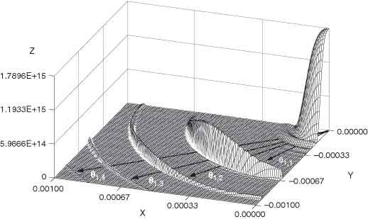
Fig. 2-5. The angular distribution of fundamental (n = 1) undulator radiation for the limiting case of zero beam emittance. The x and y axes correspond to the observation angles q and y (in radians), respectively, and the z axis is the intensity in photons·s–1·A–1·(0.1 mr)–2·(1% bandwidth)–1. The undulator parameters for this theoretical calculation were N = 14, K = 1.87, lu = 3.5 cm, and E = 1.3 GeV. (Figure courtesy of R. Tatchyn, Stanford University.)
Fig. 2-6. The function Qn(K) for different values of n.
![]() (13a)
(13a)
Away from the axis, there is also a change in wavelength: The factor (1 + K2/2) in Eq. (11) must be replaced by [1 + K2/2 + g2 (q2 + y2)]. Because of this wavelength shift with emission angle, the angle-integrated spectrum consists of peaks at ln superposed on a continuum. The peak-to-continuum ratio is large for K << 1, but the continuum increases with K, as one shifts from undulator to wiggler conditions.
B.3 Power
The total power radiated by an undulator or wiggler is
![]() (18)
(18)
where Z0 = 377 ohms, or, in practical units,
![]()
The angular distribution of the radiated power is
![]() (19)
(19)
or, in units of W·mr–2,
![]()
The behavior of the angular function fK(gq,gy), which is normalized as fK(0,0) = 1, is shown in Fig. 2-7. The function G(K), shown in Fig. 2-8, quickly approaches unity as K increases from zero.
C. EMITTANCE EFFECTS
Electrons in storage rings are distributed in a finite area of
transverse phase space—position ´
angle. We introduce the rms beam sizes sx (horizontal) and sy
(vertical), and beam divergences ![]() (horizontal) and
(horizontal) and
![]() (vertical).
The quantities
(vertical).
The quantities ![]() and
and ![]() are
known as the horizontal and vertical emittances, respectively. In general,
owing to the finite emittances of real electron beams, the intensity of the
radiation observed in the forward direction is less than that given by Eqs. (2a)
and (13a). Finite emittances can be taken into account approximately by replacing
these equations by
are
known as the horizontal and vertical emittances, respectively. In general,
owing to the finite emittances of real electron beams, the intensity of the
radiation observed in the forward direction is less than that given by Eqs. (2a)
and (13a). Finite emittances can be taken into account approximately by replacing
these equations by
 (20)
(20)
and
 (21)
(21)
for bends and undulators, respectively. For bending magnets, the electron beam divergence effect is usually negligible in the horizontal plane.
Fig. 2-7. The angular function fK, for different values of the deflection parameter K, (a) as a function of the vertical observation angle y when the horizontal observation angle q = 0 and (b) as a function of q when y = 0.
Fig. 2-8. The function G(K).
D. SPECTRAL BRIGHTNESS AND
TRANSVERSE COHERENCE
For experiments that require a small angular divergence and a small irradiated area, the relevant figure of merit is the beam brightness B, which is the photon flux per unit phase space volume, often given in units of photons·s–1·mr–2·mm–2·(0.1% bandwidth)–1. For an undulator, an approximate formula for the peak brightness is
![]() (22)
(22)
where, for example,
 (23)
(23)
and where the single-electron radiation from an axially extended source of finite wavelength is described by
 (24
(24
Brightness is shown in Fig. 2-9 for several sources of synchrotron radiation, as well as some conventional x-ray sources.
That portion of the flux that is transversely coherent is given by
 (25)
(25)
A substantial fraction of undulator flux is thus transversely
coherent for a low-emittance beam satisfying exey
![]() (l/4p)2.
(l/4p)2.
E. LONGITUDINAL COHERENCE
Longitudinal coherence is described in terms of a coherence length
![]()
For an undulator, the various harmonics have a natural spectral purity of Dl/l = 1/nN [see Eq. (12)]; thus, the coherence length is given by
![]() (27)
(27)
which corresponds to the relativistically contracted length
of the undulator. Thus, undulator radiation from low-emittance electron beams
[exey
![]() (l/4p)2]
is transversely coherent and is longitudinally coherent within a distance
described by Eq. (27). In the case of finite beam emittance or finite angular
acceptance, the longitudinal coherence is reduced because of the change in
wavelength with emission angle. In this sense, undulator radiation is partially
coherent. Transverse and longitudinal coherence can be enhanced when necessary
by the use of spatial and spectral filtering (i.e., by use of apertures and
monochromators, respectively).
(l/4p)2]
is transversely coherent and is longitudinally coherent within a distance
described by Eq. (27). In the case of finite beam emittance or finite angular
acceptance, the longitudinal coherence is reduced because of the change in
wavelength with emission angle. In this sense, undulator radiation is partially
coherent. Transverse and longitudinal coherence can be enhanced when necessary
by the use of spatial and spectral filtering (i.e., by use of apertures and
monochromators, respectively).
The references listed below provide more detail on the characteristics of synchrotron radiation.
Fig. 2-9. Spectral brightness for several synchrotron radiation sources and conventional x-ray sources. The data for conventional x-ray tubes should be taken as rough estimates only, since brightness depends strongly on such parameters as operating voltage and take-off angle. The indicated two-order-of-magnitude ranges show the approximate variation that can be expected among stationary-anode tubes (lower end of range), rotating-anode tubes (middle), and rotating-anode tubes with microfocusing (upper end of range).
REFERENCES
1. G. K. Green, “Spectra and Optics of Synchrotron Radiation,” in Proposal for National Synchrotron Light Source, Brookhaven National Laboratory, Upton, New York, BNL-50595 (1977).
2. H. Winick, “Properties of Synchrotron Radiation,” in H. Winick and S. Doniach, Eds., Synchrotron Radiation Research (Plenum, New York, 1979), p. 11.
3. S. Krinsky, “Undulators as Sources of Synchrotron Radiation,” IEEE Trans. Nucl. Sci. NS-30, 3078 (1983).
4. D. F. Alferov, Yu. Bashmakov, and E. G. Bessonov, “Undulator Radiation,” Sov. Phys. Tech. Phys. 18, 1336 (1974).
5. K.-J. Kim, “Angular Distribution of Undulator Power for an Arbitrary Deflection Parameter K,” Nucl. Instrum. Methods Phys. Res. A246, 67 (1986).
6. K.-J. Kim, “Brightness, Coherence, and Propagation Characteristics of Synchrotron Radiation,” Nucl. Instrum. Methods Phys. Res. A246, 71 (1986).
7. K.-J. Kim, “Characteristics of Synchrotron Radiation,” in Physics of Particle Accelerators, AIP Conf. Proc. 184 (Am. Inst. Phys., New York, 1989), p. 565.
8. D. Attwood, Soft X-Rays and Extreme Ultraviolet Radiation: Principles and Applications (Cambridge Univ. Press, Cambridge, 1999); see especially Chaps. 5 and 8.